
In the image below there is a low cost DC motor (in my case is a 24 Vdc motor).
This is a typical DC motor used for automate a gate, shutters, etc.
Cable connections
Brown - HALL Vcc from 3,8 to 50V
Green - HALL pulse
White - HALL GND
Blue  - Motor GND
Red   - Motor VCC
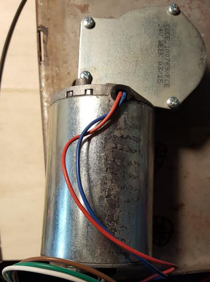
This motor mount a very interesting Honeywell Hall sensor model S566A.
This sensor return a pulse or more pulses that can be count to know the number of rotations that the motor has made.
The accuracy or resolution depends on how many magnets have been applied on the motor rotor.
In our case there are two magnets so we will have two pulses at each complete revolution of the engine.
We done some measures that are shown below.
Vcc (Vdc)     Duration of pulse (mS)
12            22
20            13
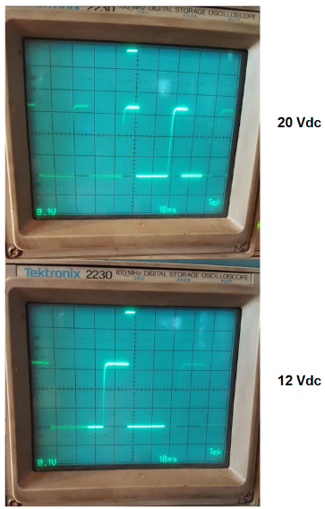
For measure this pulses we suggest to use a GPIO in External Interrupt Mode with Falling edge trigger detection.
See this tutorial.
The wiring from motor HALL encoder to NUCLEO board are shown below.
Brown - HALL Vcc   -> NUCLEO +5 Vcc and connect in series a 100 ohm resistor at PA8 or PA9
Green - HALL pulse -> NUCLEO PA8 or PA9 (see this tutorial)
White - HALL GND   -> NUCLEO GND
How to get the SW for this project
Please send us an email and ask us the password for: GPIOinterrupt
Please specify also your country and your city, this are only for our personal statistics.
Get the SW clicking here, but remember to ask us the password for open it.
NOTE:
For import this project in your ATOLLIC read this note.
NOTE:
- Use FIREFOX or CHROME for a clear view of the images present in this web site
- For enlarge the image press: CTRL +
For reduce the image press: CTRL –