- MEMS
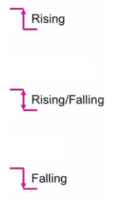
- Rising & Falling
- IP Camera
- MCU
- Microphone
- Electric Motor
- BlueTooth
- Ethernet & WiFi
- Radio
- MTBF, MTTF, etc
MEMS
- MLC – Machine Learning Core (see for example the SM330DHCX)
- FSM – Finite State Machine
- Power supply (VDD): Operating DC power supply.
Correct operation of a sensor using a power supply voltage outside of this range is not guaranteed.
The other sensor parameters in the datasheet are provided at defined VDD , e.g. VDD = +2.5 V.
It is recommended to keep VDD clean, with minimum ripple e.g. using an ultra-low-noise low-dropout regulator to power the accelerometer. - Supply current (IDD): Average current consumption of a sensor in the given operating range.
Varies depending on resolution mode selected, sensor Output Data Rate (ODR) and VDD supply voltage - Output Data Rate (ODR): Rate at which new sensor data are available to the user g: this is unit of acceleration for accelerometers: 1g is equal to 9.81m/s2 °/s or dps (degree per second): This is the unit of rate for gyroscopes.
- Gauss/Tesla: This is the unit of measurement for magnetometers.
- hPa and mbar: These are the units of measurement for atmospheric pressure sensors.
- Full Scale (FS): It defines the range of acceleration values that can be measured.
If the sensor is temporally exposed to high levels out of the range, no damage is expected unless a critical value is applied; For ST accelerometers, the maximum value which does not result in permanent damage is 10000g for 0.1ms. - Turn-on time (tON): This parameter defines the time required before the MEMS sensor is ready to output measured sensor data after exiting power-down mode.
- Bandwidth (BW): Bandwidth (in Hz) is the frequency range in which the MEMS sensor operates. Our sensors respond from DC to a user-definable upper cut-off frequency. The maximum bandwidth is determined by the mechanical resonant frequency of the sensor. Example: When ODR = 100 Hz, BW is typically 50 Hz with a built-in low-pass filter. The system recognizes any motion below 50 Hz. If the system has dynamic motion higher than 50 Hz, then the ODR needs to be increased to a higher setting in order to cover all useful system signals.
- Resolution and Noise Density: Resolution (in mg) is the minimum detectable change in acceleration. The resolution is the acceleration noise density (in mg/√Hz) integrated over the signal bandwidth.
- Sensitivity: Sensitivity level (in LSb/g), also known as gain, is the output change per unit of input acceleration.
This value changes very little over temperature (see sensitivity change vs. temperature in the datasheet) and also very little over time. The sensitivity tolerance describes the range of sensitivities of a large population of sensors. - Sensitivity change vs. temperature (TCSo): This parameter defines how the sensitivity of the sensorchanges with temperature.
For example for an accelerometer, at a ±2.0 g full-scale range, the sensitivity changes within ±0.01%/°C.
Therefore, if the environmental temperature changes 40 °C, from 25 °C to 65 °C, then the sensitivity changes within the range of ±0.01% * 40 = ±0.4%, which means the sensitivity change over 40 °C is within 0.996 mg/LSB and 1.004 mg/LSB, which shows that the sensitivity is very stable versus temperature change.
Thus, temperature compensation for sensitivity can be ignored. - Non Linearity: (in % of FS) The sensors do not demonstrate a perfectly linear relationship between input acceleration and output value.
This non-linearity is the maximum deviation of output voltage from the “best-fit line”, the straight line defined by sensitivity, expressed in percentage of Full-Scale Output. - Zero-g level (offset): (in mg) describes the actual output signal when no acceleration is applied. The lower, the better.
- Cross-axis Sensitivity: It represents the output induced on an axis from the application of acceleration on a perpendicular one and it’s expressed as a percentage of this acceleration value.
There are multiple cross-axis sensitivities: Sxy, Sxz, Syx, Syz, Szx, Szy, where the first subscript is the sensing axis and the second subscript is the off-axis direction. - AEC-Q100: All integrated circuits must be tested for compliance with AEC-Q100 before they can be marketed as an automotive-grade device.
Rising & Falling
Microphone
IP Camera
NTP
Network Time Protocol will synchronize your camera with an Internet time server.
SMTP
Simple Mail Transfer Protocol (SMTP) is an Internet standard for electronic mail (e-mail) transmission. See here.
H.264
H.264/MPEG-4 Part 10 or AVC (Advanced Video Coding) is a video compression format that is currently one of the most commonly used formats for the recording, compression, and distribution of video content.
For more info see the:
Everything You Should Know about H.264/AVC (Advanced Video Coding)
See here.
Media Port
The Media Port is used to transfer video stream, and the default port no. is 888, you can reset the port no. between 1 ~65535
UPnP
Universal Plug and Play (UPnP) is a set of networking protocols that permits networked devices, such as personal computers, printers, Internet gateways, Wi-Fi access points and mobile devices to seamlessly discover each other’s presence on the network and establish functional network services for data sharing, communications, and entertainment.
UPnP is intended primarily for residential networks without enterprise-class devices.
See here.
Resolution
The camera support a different resolution, 720P, VGA, 1/4 VGA, etc.
High resolution give the top of video but the code flux will become larger to, an it will take up more bandwidth.
Camera Bit Rate
Generally speaking, the larger the bit rate and the clear video will become.
But the bit rate configuration should combine well with the network bandwidth.
When the network bandwidth is very narrow, and the bit rate is large, that will lead to video can not play well.
Key Frame Interval
It is the time between las key frame. The shorter the duration, the more likely you will get a better video quality, but at the cost of higher network bandwidth consumption.
PTZ camera
PTZ camera is a camera that is capable of remote directional and sometime there is also the zoom control. See here.
MCU – Micro Controller Unit
CMSIS
Cortex Microcontroller Software Interface Standard, see here
USB
Introduction to USB
Developing USB applications using the STM32 ARM Cortex-M3 microcontroller by: Anis BEN ABDALLAH
USB HS – High-speed (480 Mbit/s)
USB FS – Full-speed (12 Mbit/s)
USB LS – Low-speed (1.5 Mbit/s)
USB On-The-Go – for more info click here
AWU
Auto Wake-Up – Normaly is under control of Timer or RTC
CAN
Controller Area Network
LIN
Local Interconnect Network
CF
Compact Flash
MMC
Multi Media Card
SD
Secure Digital
SDIO
Secure Digital Input Output
The SDIO adapter block provides all functions specific to the MMC/SD/SD-I/O card such as the clock generation unit, command and data transfer.
For more info click here
CRC
Cyclic Redundancy Check
For more info click here
DMA
Direct Memory Access
Tranfer data is normaly possible from/to:
Memory-to-memory, peripheral-to-memory, memory-to-peripheral transfers and peripheral-to-peripheral
for more info click here
EXTI
External Interrupt
WDG
Watchdog – for more info click here
WWDG
Window Watchdog – for more info click here
ETM
Embedded Trace Macrocell
EMI
External Memory Interface – for more info click here
FSMC
Flexible Static Memory Controller – for more info click here
NWG
Noise Wave Generation
IrDA
Infrared Data Association
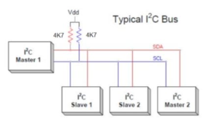
I2C (Inter-Integrated Circuit), see here (Wikipedia)
I2S
Inter-IC Sound
The I2S protocol is used for audio data communication between a microcontroller/DSP and an audio Codec/DAC.
For more info click here
SPI
Serial Peripheral Interface – see also SPI Page
USART
Universal Sync Async Receiver Trasmitter
UART
Universal Async Receiver Trasmitter
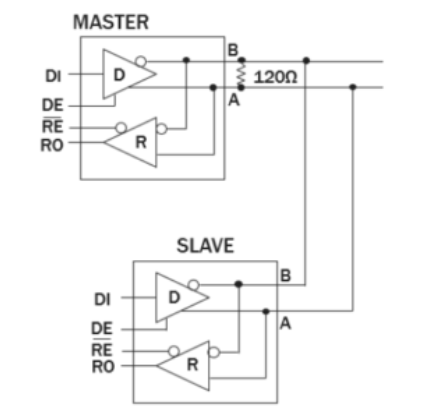
RS485 – see here (Wikipedia)
See this page (Italian)
See this page (English) and also see here and here
A video tutorial is here.
MII
Media Indipendent Interface (normally used for connect a ethernet interface)
RMII
Reduced Media Indipendent Interface (normally used for connect a ethernet interface)
MCU
Micro Controller Unit – is a single chip that contains a Processor, RAM, ROM, clock, I/O, timers, USB, etc.
DSC
Digital Signal Controllers
DSP
Digital Signal Processor
FPU
Floating Point Unit
HSE
High Speed External oscillator
HSI
High Speed Internal RC
LSI
Low Speed Internal RC
LSE
Low Speed External oscillator
CSS
Clock Security System that backup clock in case of HSE clock failure
PDR
Power Down Reset
POR
Power On Reset
PVD
Programmable Voltage Detector
RTC
Real Time Clock
IO or I/O
Input Output
PWM
Pulse Width modulation – Is normally one of the Timer functionality
PLL
Phase Locked Loop or Phase Lock Loop
ADC
Analog to Digital Converter – see also AD Page
DAC
Digital to Analog Converter
ART Accelerator™
Adaptive Real-Time memory accelerator, see STM32F2 & STM32F4 user manual for detail
Big-endian & Little-endian
See this page
Ethernet MAC 10/100
For more info click here
In the document above you find description of:
Physical Layer
Data Link Layer
Network Layer
Transport Layer
Session Layer
Presentation Layer
Application Layer
ISO OSI Model
OSI Layers
ISO OSI vs. TCP/IP
ISO OSI vs. Real Time Ethernet
TCP/IP vs. OSI
TCP/IP Stack
TCP Protocol
TCP Segment Structure
TCP Ports
IP Protocol
IP Packet Structure
UDP
UDP vs. TCP
UDP Datagram
UDP Ports
Packet Terminology Overview
TCP/IP Stacks–
FIT – Failure in time, see for example this manual.
CCF – Common cause failure
CM – Continuous mode
COTS – Commercial off-the-shelf
CoU – Conditions of use
CPU – Central processing unit
CRC – Cyclic redundancy check
DC – Diagnostic coverage
DMA – Direct memory access
DTI – Diagnostic test interval
ECM – Engine control module
ECU – Electronic control unit
EUC – Equipment under control
FIT – Failure in time
FMEA – Failure mode effect analysis
FMEDA – Failure mode effect diagnostic analysis
HD – High demand
HFT – Hardware fault tolerance
HW – Hardware
ITRS – International technology roadmap for semiconductors
LD – Low demand
MCU – Microcontroller unit
MTBF – Mean time between failure
MTTFd – Mean time to failure
PDS(SR) – Power drive system (safety related)
PEc – Programmable electronics – core
PEd – Programmable electronics – diagnostic
PFD – Probability of dangerous failure on demand
PFH – Probability of failure per hour
PL – Performance level
PST – Process safety time
SFF – Safe failure fraction
SIL – Safety integrity level
SRCF – Safety-related control function
SRECS – Safety-related electrical control systems
SRP/CS – Safety-related parts of control systems
Electric Motor
See also here
FOC
Field Oriented Control
Control algorithm often used for PMSM motors
PSM
Permanent Magnet Syncrhronous Motor
BLDC
BrushLess DC Motor
See here.
ACIM
3-phase induction motor
How to convert RPM to the Frequency, see here.
BlueTooth
Link n.1
Link n.2
WikipediA (English)
WikipediA (Italian)
Beacons or iBeacons – small objects transmitting location information to smartphones and powered by Bluetooth Smart
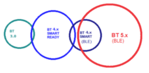
Up to now there are different release of BT, for example there is v2.1, v3.0, BTLE v.4.x and 5.x
For see the differences from the different release of BT see here and here.
Here I want to highlight the differences inside the BT
The latest Bluetooth version 4.x boasts two additional certifications:
Smart Ready and Smart .
BT 4.x Smart Ready identifies the dual-mode support or compatibility with older standards and more advanced features.
BT 4.x Smart is for simple devices that aim to reduce consumption, this version is NOT copatible with the older BT standards.
Generic Access Profile (GAP)
Service Discovery Application Profile (SDAP)
Cordless Telephony Profile (CTP)
Intercom Profile (IP)
Serial Port Profile (SPP)
Headset Profile (HSP)
Dial-up Networking Profile (DUNP)
Fax Profile
LAN Access Profile (LAP)
Generic Object Exchange Profile (GOEP)
Object Push Profile (OPP)
File Transfer Profile (FTP)
Synchronization Profile (SP)
Personal Information Manager (PIM)
Hands-Free Profile (HFP)
Human Interface Device Profile (HID)
Hard Copy Replacement Profile (HCRP)
Basic Imaging Profile (BIP)
Personal Area Networking Profile (PAN)
Basic Printing Profile (BPP)
Advanced Audio Distribution Profile (A2DP)
Audio Video Remote Control Profile (AVRCP)
Sim Access Profile (SAP)
Extended data packet length – Optional BLE 4.2 feature supported over BlueNRG-2 used to increase data transfer rates (up to 700 kbps).
Secure connection– Optional state-of -the-art BLE feature supported over BlueNRG-2 to improve connection security.
FOTA – Firmware (application & stack) Over-The-Air upgrade. The procedure allows to push new firmware on a device deployed in the field.
BLE Profile –A basic collection of attributes (services and characteristics) exposed by a device in order to share user data over a BLE link.
GATT – Generic Attribute Profile software layer (part of the BLE stack) that defines how attributes are organized and how the application can access them.
Advertising – Bluetooth devices send advertising packets (PDUs) to broadcast data, and to allow other devices (scanners) to find and connect to them. The advertising data consists of up to 31 bytes of user configurable data.
Scan rsp – An additional 31 bytes can be sent as a scan responseto a scan request (scan request sent from client device such as smartphone).
Beacon – A beacon device uses advertising mode to share data with users.
The payload can be specified such as Ibeacon (Apple) and Eddystone (Google) or can be configured by application.
New Bluetooth profiles (4.x)
- Bluetooth HID over GATT: It ensures minimal latency to the low-power devices like mice, keyboards and joysticks.
- Bluetooth MAP: Allows you to improve the interaction to other Bluetooth devices such as integrated systems of automobiles or other Android device.
BLE – Quick Reference Guide
Ethernet & WiFi
ADSL – VDSL
AP – Access Point
BSP – Base Support Package
DHCP – In telecomunicazioni e informatica il Dynamic Host Configuration Protocol (DHCP) (protocollo di configurazione IP dinamica) è un Protocollo Applicativo (Ausiliario) che permette ai dispositivi o terminali di una certa rete locale di ricevere automaticamente ad ogni richiesta di accesso, da una rete IP (quale una LAN), la configurazione IP necessaria per stabilire una connessione e operare su una rete più ampia basata su Internet Protocol, cioè interoperare con tutte le altre sotto-reti scambiandosi dati, purché anch’esse integrate allo stesso modo con il protocollo IP. Il protocollo è implementato come servizio di rete ovvero come tipologia di server: ad es. nei sistemi Unix e Unix-like è implementato nel demone dhcpd, in quelli basati su Active Directory di Microsoft e/o Windows Server dal servizio server dhcp. (From Wikipedia)
In telecommunications and IT, the Dynamic Host Configuration Protocol (DHCP) is an Application Protocol (Auxiliary) that allows devices or terminals of a certain local network to automatically receive at every access request, from an IP network. (such as a LAN), the IP configuration necessary to establish a connection and operate on a larger network based on the Internet Protocol, i.e. interoperate with all the other sub-networks by exchanging data, provided they are also integrated in the same way with the IP protocol . The protocol is implemented as a network service or as a type of server: e.g. in Unix and Unix-like systems it is implemented in the dhcpd daemon, in those based on Microsoft Active Directory and / or Windows Server by the dhcp server service. (From Wikipedia)
DNS – In informatica e telecomunicazioni il sistema dei nomi di dominio (in inglese: Domain Name System, DNS), è un sistema utilizzato per assegnare nomi ai nodi della rete (in inglese: host). Questi nomi sono utilizzabili, mediante una traduzione, di solito chiamata “risoluzione”, al posto degli indirizzi IP originali. Il servizio è realizzato tramite un database distribuito, costituito dai server DNS. Il DNS ha una struttura gerarchica ad albero rovesciato ed è diviso in domini (com, org, it, ecc.). Ad ogni dominio o nodo corrisponde un nameserver, che conserva un database con le informazioni di alcuni domini di cui è responsabile e si rivolge ai nodi successivi quando deve trovare informazioni che appartengono ad altri domini. (from: Wikipedia)
In IT and telecommunications the domain name system (in English: Domain Name System, DNS), is a system used to assign names to nodes on the network (in English: host). These names can be used, by means of a translation, usually called “resolution”, instead of the original IP addresses. The service is implemented through a distributed database, consisting of DNS servers. DNS has a hierarchical structure with an inverted tree and is divided into domains (com, org, it, etc.). Each domain or node corresponds to a name-server, which maintains a database with the information of some domains for which it is responsible and turns to subsequent nodes when it has to find information belonging to other domains. (from: Wikipedia)
HAL – Hardware Abstraction Layer
HTML -Hyper Text Markup Language
HTTP – Hyper Text Transfer Protocol
IBSS – Independent Basic Service Set.
An IBSS is a set of STAs configured in ad hoc (peer-to-peer)mode. (from: Wikipedia)
Per Italiano vedere qui.
ISP – Internet Service Provider, in other words, it is your internet connection provider.
For more info see here (English) or qui (Italiano).
Mini-AP – Mini Access Point
MTU – Maximum Transmission Unit
In computer networking, the maximum transmission unit (MTU) is the size of the largest protocol data unit (PDU) that can be communicated in a single network layer transaction. (from: Wikipedia)
Vedere qui e qui per Italiano.
SNMP – Il Simple Network Management Protocol (SNMP) è un protocollo a livello applicazione definito dall’IAB (Internet Architecture Board) nell’RFC1157 per lo scambio di informazioni di gestione tra dispositivi di rete. Il protocollo fa parte della suite di protocolli TCP⁄IP (Transmission Control Protocol⁄Internet Protocol).
The Simple Network Management Protocol (SNMP) is an application-level protocol defined by the Internet Architecture Board (IAB) in RFC1157 for the exchange of management information between network devices. The protocol is part of the Transmission Control Protocol⁄Internet Protocol (TCP⁄IP) suite of protocols.
SSID – Service Set Identifier
STA – Station mode
TCP – Transmission Control Protocol
UDP – User Datagram Protocol
UPnP – Universal Plug and Play (UPnP) è un protocollo di rete creato dall’UPnP Forum. L’obiettivo della tecnologia UPnP è quello di permettere a diversi terminali di connettersi l’uno all’altro e di semplificare drasticamente l’utilizzo di reti domestiche (condivisione dati, comunicazioni e intrattenimento) e aziendali. Il termine UPnP deriva da Plug and play che in inglese significa letteralmente Inserisci e utilizza e che indica la possibilità di utilizzare un componente non appena viene connesso al computer o alla rete. (From Wikipedia)
Universal Plug and Play (UPnP) is a network protocol created by the UPnP Forum. The goal of UPnP technology is to allow different terminals to connect to each other and to drastically simplify the use of home (data sharing, communications and entertainment) and corporate networks. The term UPnP derives from Plug and play which in English literally means Insert and use and which indicates the possibility of using a component as soon as it is connected to the computer or to the network. (From Wikipedia)
WiFi – Wireless LAN based on IEEE 802.11
WIND – WiFi Indication
WLAN – Wireless Local Area Network
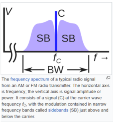
Radio
dBc/Hz – (decibels relative to the carrier), is the power ratio of a signal to a carrier signal, expressed in decibels. (From Wikipedia)
Carrier Wave (From Wikipedia)
S/N – SNR
Signal to noise ratio, SNR, S/N, is used to define the sensitivity performance of radio communications equipment. For more info see here.
RF Link Budget
Link Budget (dB) = Tx Power Level (dBm) –Receiver Sensitivity Level (dBm)
RSSI – Received signal strength indicator (RSSI) is a measure of the power present in a received radio signal.
dBm –A unit of measure of the absolute radio power level in decibels scale vs 1mW of power. It means:
1 mW is 0 dBm,
10 mW is 10 dBm,
100 mW is 20 dBm, etc…
dB – The measure of the relative difference between 2 radio power levels. This is expressed in log10 scale which is more convenient for such measurements.
DCDC converter – An electronic circuit that provides an output regulated voltage that is different (higher / lower) than its input voltage. In a radio chipset and battery-operated system, its purpose is to convert the battery voltage to a lower regulated level (also called a “buck converter”).
RF balun – This RF circuit filters RF signals (ensuring compliance with local radio regulations such as ETSI, FCC, and ARIB) and performing 50-Ohm adaptation with an antenna connector to ensure optimal RF transmission and reception performance.
PLL – Phase Lock Loop is a circuit that generates the required phase or frequency in a radio system. This is basis of the analog part of a radio transceiver to perform radio modulation & demodulation.
HS XTAL – High-speed crystal oscillator required to provide the reference frequency to the PLL in order to generate the correct RF frequency.
Xtal Ppm – Parts per million frequency inaccuracy of the crystal means the maximum frequency offset of the crystal oscillator. As the Crystal is used to feed the reference frequency to the transceiver PLL, it means that the RF transceiver application is affected by the crystal tolerance. As an example, a ±10ppm Xtalin a 868 MHz radio band leads to maximum ±8.68 kHz deviation from the desired channel frequency.
AFC – Automatic Frequency Compensation is a Receiver feature that measures and corrects a transmitter’s frequency offset. Frequency offset is introduced by HS Xtalppm.
TCXO –Temperature Compensated Crystal Oscillator is a high-speed crystal that has ultra-low frequency variation thanks to temperature measurement & compensation circuitry. This architecture ensures a very accurate frequency regardless of the application temperature.
RO – A ring oscillator is an internal circuit (low-cost vs external 32 kHz crystal oscillator) that is required for low-power management of transceivers. Internal transceiver timers run based on the RO frequency.
PCB antenna – PCB antenna is designed on a printed circuit board using copper lines. Its advantage in terms of cost is that its one-quarter wavelength ensures good RF performance.
50 Ohm adaptation – In RF applications, all measurements are based on 50-Ohm connectors to ensure a reference setup for radio & power consumption measurements. Moreover it eases radio designs with antennas which are close to 50-Ohms impedance.
FSK modulations – modulations proposed by transceiver include:
Frequency Shift Keying modulations (FSK) with either 2-frequency (2-FSK) or 4-frequency (4-FSK)
The principle of FSK modulations is to change the binary encoding by changing the frequency of the transmitted signal.
GFSK is also defined to smooth binary transitions to ease compliance with local radio regulations (ETSI, FCC, and ARIB).
The principle of FSK modulations is to change the binary encoding by changing the frequency of the transmitted signal.
OOK is amplitude modulation (On Off Keying) which means turning power on/off to modulate data.
SINAD Signal to Noise And Distorsion, is a measure of the quality of a signal from a communications device. SINAD is usually expressed in dB and is quoted alongside the receiver RF sensitivity.
For example: Receiver sensitivity: 0.25 μV at 12 dB SINAD.
More info are here.
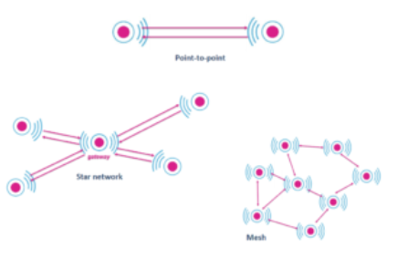
Network topolgy
Sub-1GHz Quick Reference Guide
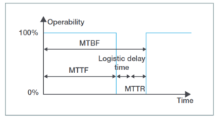
MTBF
- MTTF = Mean Time To Failure
- MTTR = Mean Time To Repair
- MTBF = Mean Time Between failure = MTTF + MTTR
- MTBF Calculation formula is here