
For develop this project the use the NUCLEO_L031K6 (32 pin Nucleo Board), CUBE-MX and ATOLLIC.
We assume that you have familiarity with this tools, in other case see our dedicate tutorials to CUBE-MX and ATOLLIC.
ATTENTION:
Now we suggest to use the STM32CubeIDE that include ATOLLIC and CUBE-MX.
First is necessary configure the NUCLEO_L031K6 ADC pins and some other using the CUBE-MX.
The global MCU configuration is shown below.
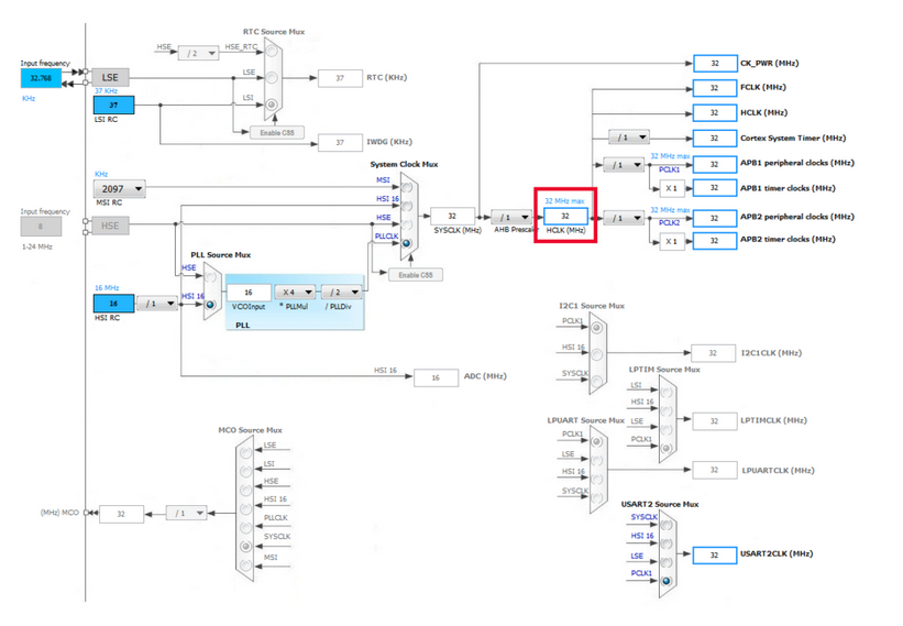
Below there is the Clock configuration. We use 32Mhz.
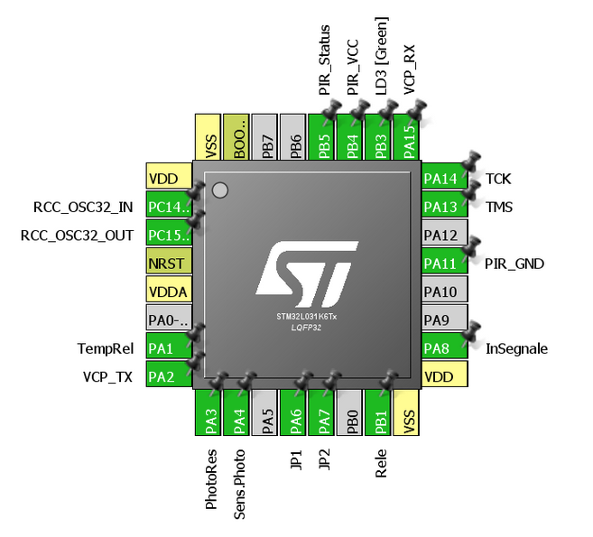
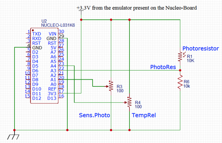
On NUCLEO_L031K6 we use the ADC pins:
PA1 (TempRel)
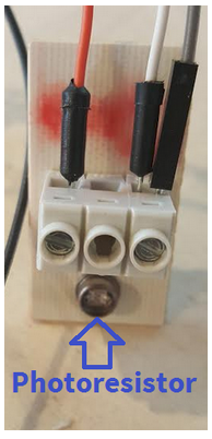
PA3 (PhotoRes)
PA4 (SensPhotoRes)
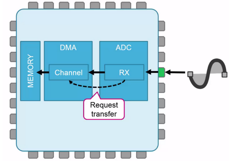
It is important to set the ADC in Continuous Conversion Mode and ENABLE the DMA, see below.
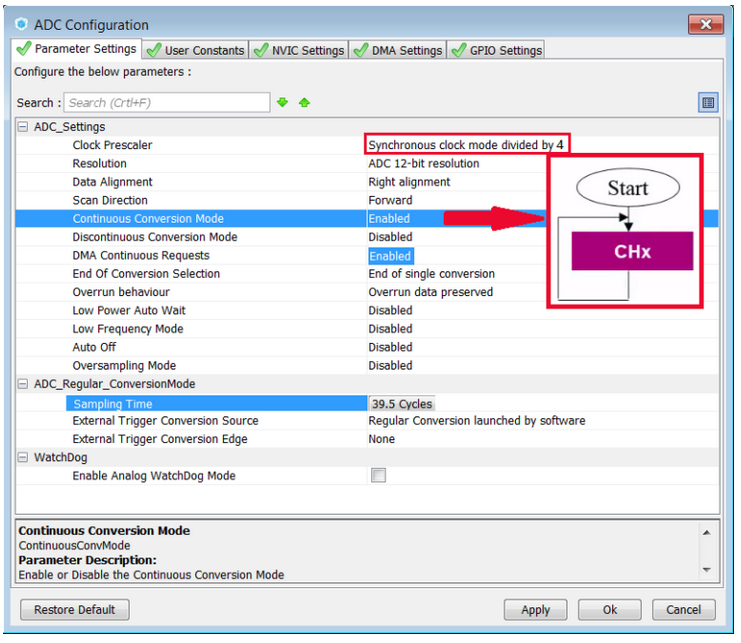
We select the ADC Clock Prescaler to: Synchronous Clock mode divided by 4
This is for avoid the owerclock of ADC peripheral.
Refer the User Manual fo STM32L031 (see the ADCCLK and its prescaler).
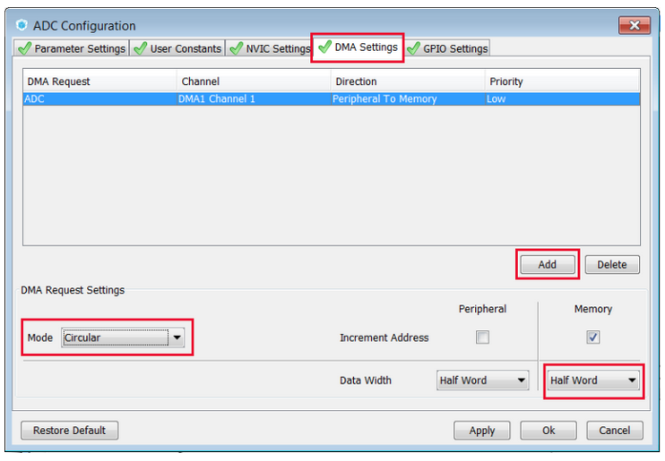
Now is necessary add the DMA channel to the ADC.
Select the DMA tab and press the ADD button. See below.
Remember also to ENABLE the CIRCULAR mode for DMA, see below.
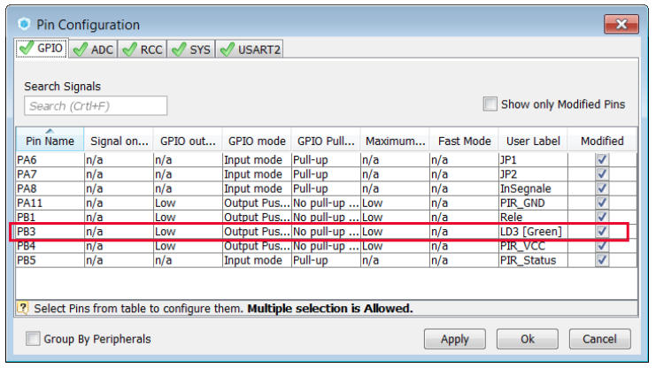
Also enable the LED (LD3) that we will use to see the result of our SW.
This explanation is extracted from our more complex project that we will publishing in the future on this website.
It’s for this reason that there are some more PINs configured in the CUBE-MX that here are not used.
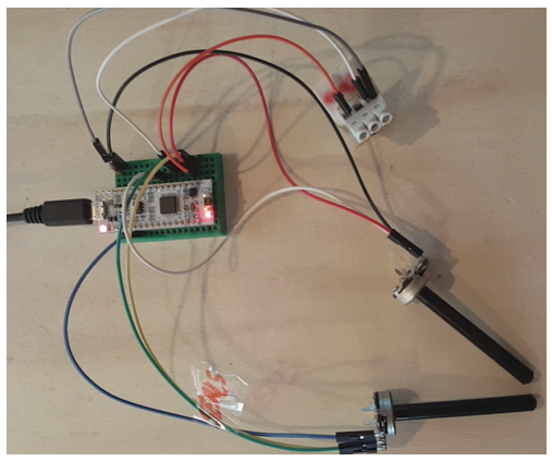
The schematic used here is show below.
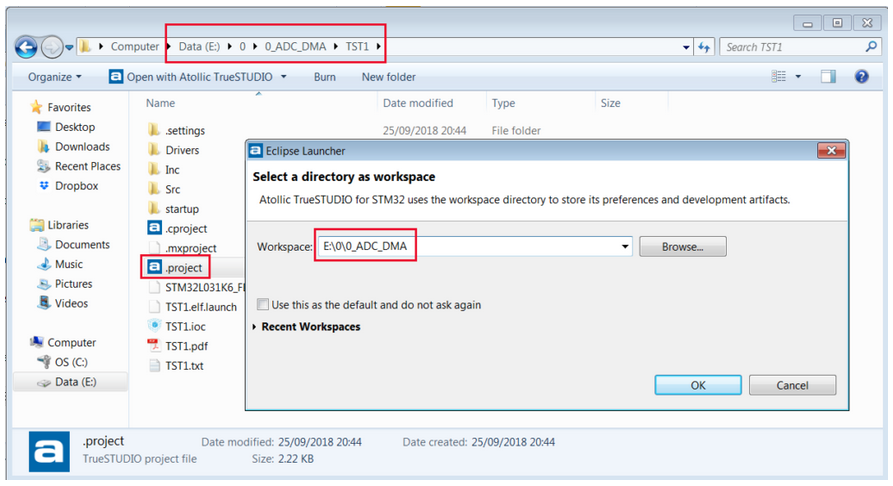
Now generate the project for your prefered IDE, here we use ATOLLIC (TrueSTUDIO).
Open the ATOLLIC project.
Now is necessary insert some lines of code in main.c for use the ADC, see below.
Between the line:
/* USER CODE BEGIN PV */
/* Private variables ———————————————————*/
and the line:
/* USER CODE END PV */
Insert the below line:
uint16_t adcBuffer[3]; // Buffer for store the results of the ADC conversion
Between the line:
/* USER CODE BEGIN 2 */
and the line:
/* USER CODE END 2 */
Insert the below line:
HAL_ADC_Start_DMA(&hadc, (uint32_t*)adcBuffer, 3); // Start ADC in DMA mode and declare the buffer where store the results
Between the line:
/* USER CODE BEGIN 3 */
and the lines:
}
/* USER CODE END 3 */
Insert the below lines:
if (adcBuffer[1] < adcBuffer[0]) // Dark – LED ON
HAL_GPIO_WritePin(LD3_GPIO_Port, LD3_Pin, GPIO_PIN_SET);
else // Sun – LED OFF
HAL_GPIO_WritePin(GPIOB, GPIO_PIN_3, GPIO_PIN_RESET);
HAL_Delay(10);
/* Infinite loop */
/* USER CODE BEGIN WHILE */
while (1)
{

/* USER CODE END WHILE */

/* USER CODE BEGIN 3 */
if (adcBuffer[1] < adcBuffer[0]) // Dark - LED ON
   HAL_GPIO_WritePin(LD3_GPIO_Port, LD3_Pin, GPIO_PIN_SET);
else // Sun - LED OFF
   HAL_GPIO_WritePin(GPIOB, GPIO_PIN_3, GPIO_PIN_RESET);

HAL_Delay(10);
}
/* USER CODE END 3 */

}
That is all, try the code.
You must see the LD3 status that change from ON/OFF depending of the light intensity (PhotoRes) and of the value of the R3 (Sens.Photo).
Here there is a video.
How to get the SW for this project
Please send us an email and ask us the password for: ADC+DMA
Please specify also your country and your city, this are only for our personal statistics.
Get the SW clicking here, but remember to ask us the password for open it.
NOTE:
- Use FIREFOX or CHROME for a clear view of the images present in this web site
- For enlarge the image press: CTRL +
For reduce the image press: CTRL –