
UNDER DEVELOPING
Introduction
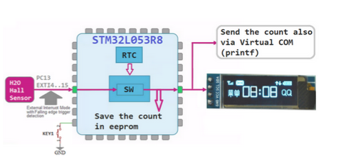
H2O flow meter is based on hall H2O sensor and the NUCLEO-L053R8 (STM32L053R8 mcu).
Thanks to this SW/HW you can take under control your water consumption.
The consumption are show on the display and also send via Virtual Com to the PC but are also stored in the internal EEPROM of STM32L053R8.
Hall H2O Sensor
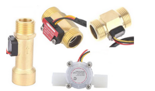
For this example we used the:
- Hall H2O flow counter, see here. We used this sensor.
- NUCLEO-L053R8 (based on the STM32L053R8)
- STM32CubeIDE (ver.1.4)
- SSD1306 I2C OLED display
STM32L053 and HAL library documentation
- STM32L053R8 data sheet is here
- The Reference Manual for STM32L053R8 is here (RM0367)
- The Reference Manual for HAL/LL manual for STM32L0 library (UM1749)
Operating Mode
It’s possible use this H2O meter in two way:
… Standalone
… Connect to the PC via USB (Virtual Com)
In standalone mode, on the display, you see the:
-> actual water consumption and
-> the last month consumption
Using the button KEY1 is possible:
-> at power on if KEY1 is pressed it clear all the EEPROM
-> if KEY1 is press, during the normal execution of the sw, it’s show in sequence the consumption registered during the months before.
Connected to the PC (you must connect the USB connector of the NUCLEO-L053R8 to the PC) you have the possibility to see consumption in real time, configure the RTC, see the contents of EEPROM and more.
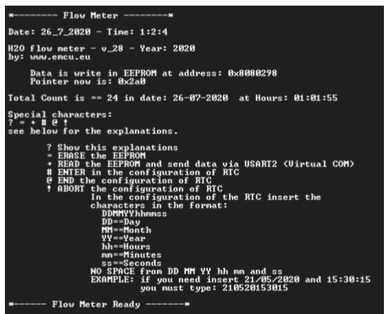
The command available are show below.
? Show explanations
= ERASE the EEPROM
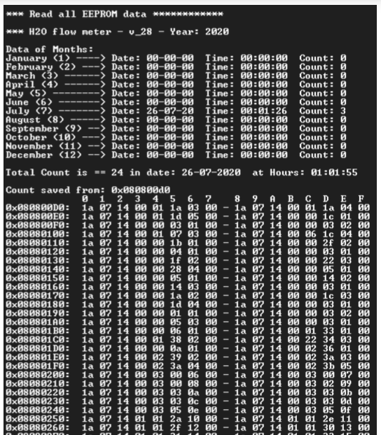
+ READ the EEPROM and send data via USART2 (Virtual COM)
# ENTER in the configuration of RTC
@ END the configuration of RTC
! ABORT the configuration of RTC
On the PC, we suggest to use Tera Term configured as show below:
Speed: 115200
Data: 8 bit
Parity: None
Stop bits: 1 bit
Flow control: None
Images
Below some images of the messages received on PC via Virtual Com.
I/O
The I/O used on NUCLEO-L053R8 are in the red boxes below.
NOTE:
The jumper JP1 must be present if you power the NUCLEO via an external USB power supply.
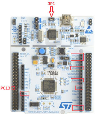
- JP1 – must be present if you power the NUCLEO via an external USB power supply.
- D15/D14 – (PB6/PB7) I2C. It’s used for connect the SSD1306 I2C OLED display, for more info see here.
- D13 – (PA5) is the Green LED present on the NUCLEO
- A0 – (PA0) is ADC reserved for monitor external power supply
- D0/D1 – (PA4/PA2) are used for USART2 for communicate to the PC (Virtual Com via NUCLEO USB)
- PC13 – is the HALL input signal (also connected to B1, Blue Button present on the NUCLEO)
- D7 – (PA8) InPut for KEY1
- D9 – (PC7) is reserved for Output
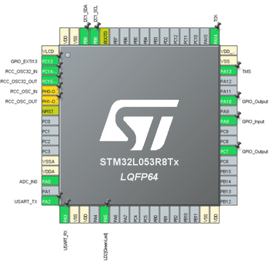
PINs allocation
Below there is the pins allocation in the IOC file.
NOTE:
We moved the output I2C1 pins in the position PB8 and PB9.
The I2C1 is used for drive the SSD1306 I2C OLED display.
For more info concerning the SSD1306 see here.
IOC file configuration report is here.
Schematic is below, here there is the PDF file.
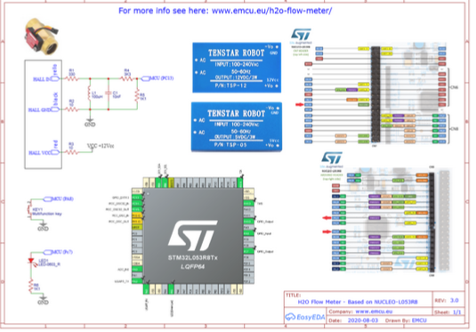
We display the results on the Display and using Virtual Com port we also send the results to the PC, thanks to emulator integrated in the NUCLEO board.
For more info concerning printf via usart see this tutorial.
Also we save the H2O Flow Count in internal EEPROM with Date and Time (by RTC).
For more info regarding RTC see the AN4759 and this tutorial.
Extra Info
- Functions explanation used in this project.
- Preliminary release of the code is in this page but is only for internal use.
- X-CUBE-RTC – Real Time Clock (RTC) software expansion for STM32Cube (AN4759)
- For more info concerning printf via usart see this tutorial.
- How to use – UART Interrupt
Power Supply NOTE:
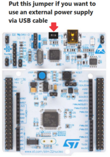
NOTE:
- Use FIREFOX or CHROME for a clear view of the images present in this web site
- For enlarge the image press: CTRL +
For reduce the image press: CTRL –