
Now there is a new tutorial that explain how to use TIMER in PWM mode with spreadsheet for calculate the values of PRESCALER, PERIOD and PULSE that is here.
In the same tutorial we explain also the redirect of printf via USART2 and getchar via USART2 in interrupt mode
- Introduction (Basic Timer)
- The PERIOD formula
- TIM in PWM mode
- How to get the SW for PWM mode
- Some note regarding the Period and Prescaler values
Introduction (Basic Timer)
STM32 contain different TIMER with different features, we start to analyze the Basic TIMER.
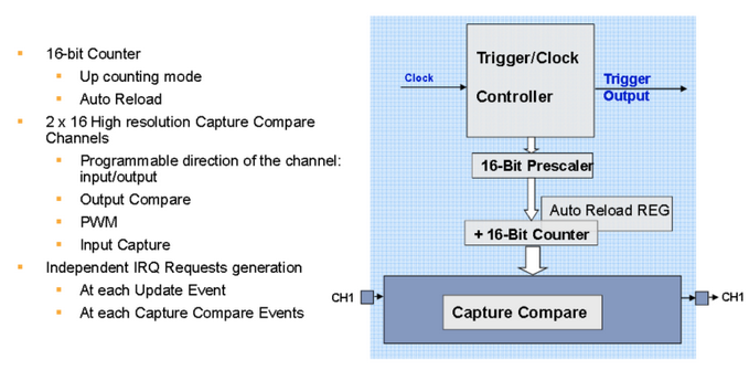
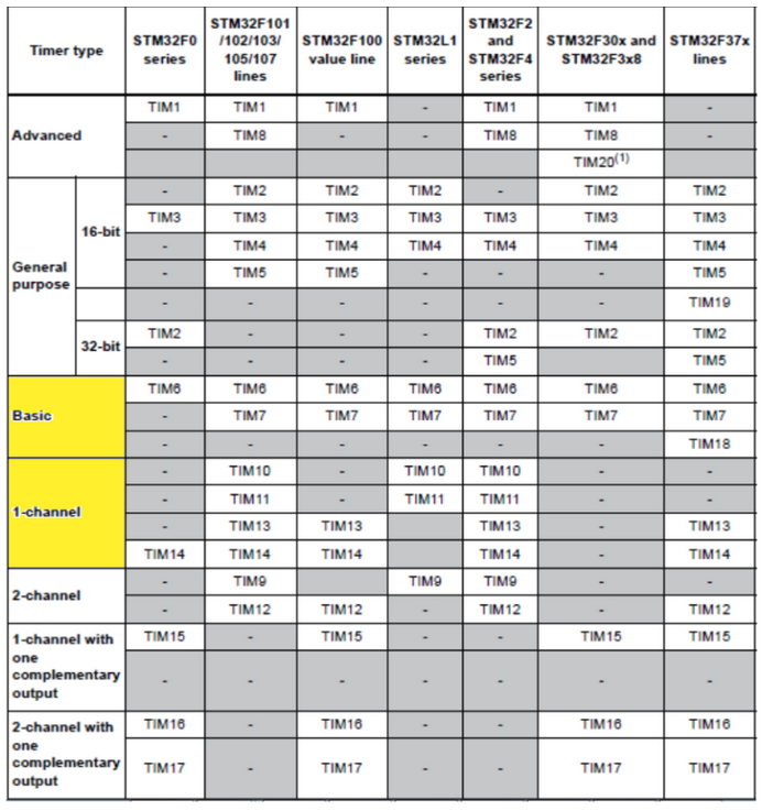
The Basic Timers (BT) are normally:
TIM6, TIM7, TIM14, etc (Consult the manual of the STM32 that you want to use)
and are the most simple timers available in the STM32 portfolio.
BT main features:
- 16 bit timer
- UP timer
- My be used in DMA and/or under Interrupt
- Has the capabilities show below
Please refer to the AN4013 for more info on the STM32 Timers.
Up to now (Feb.2018) the timers are divided as shown below.
Please check the manual of your STM32 that you need to use.
Now we explain how to use TIM14 (BT) for generate an Interrupt every 1 sec
For this first example we use the NUCLEO-F030R8, CUBE-MX and ATOLLIC.
NOTE:
Now 2021 we suggest to use the STM32CubeIDE instead CUBE-MX and ATOLLIC.
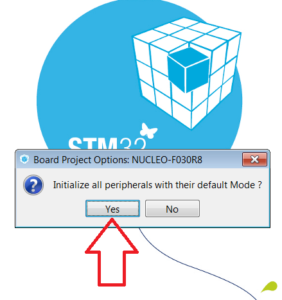
Open CUBE-MX and create a new project.
Choose the NUCLEO-F030r8 board and from the window that compare select YES, see below.
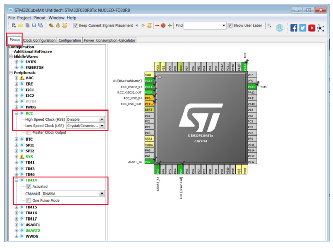
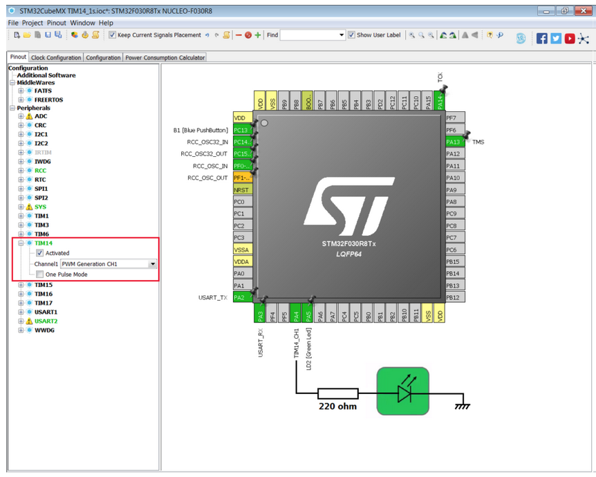
From the PINOUT tab configure the RCC and TIM14 has show below.
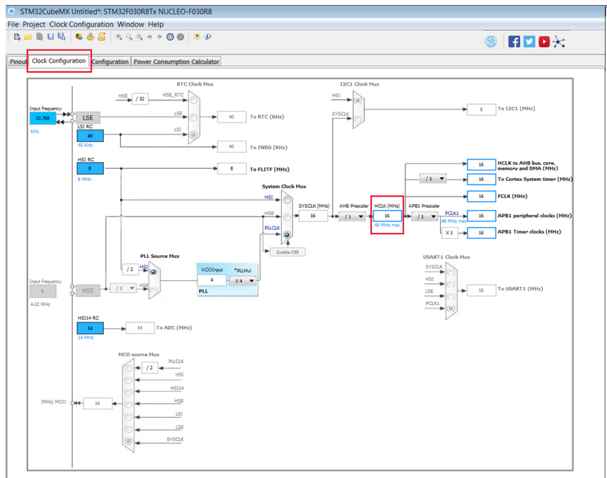
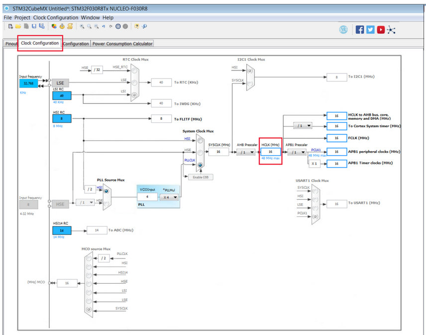
In CLOCK tab configure the HCLK clock to 16 Mhz, see below.
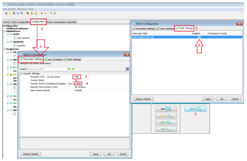
Now select the CONFIGURATION tab and configure the TIM14 parameters as show below.
PRESCALER – 999 (It’s for obtain a period of 1s)
COUNTER PERIOD – 15999 (It’s for obtain a period of 1s)
16000000 / 999 / 15999 = 1 (1s)
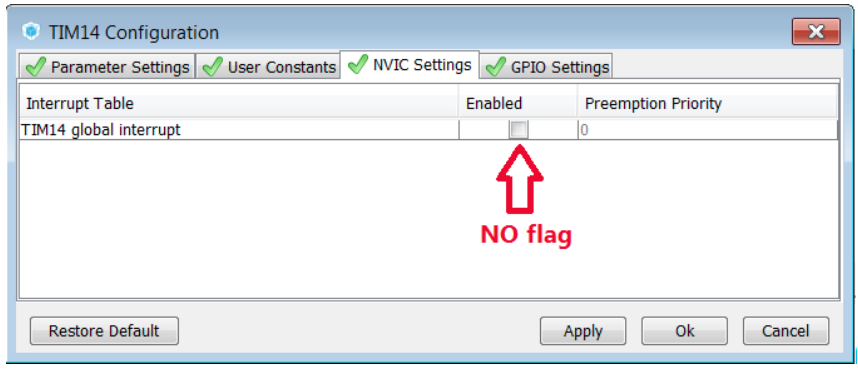
ENABLE TIM14 Global Interrupt
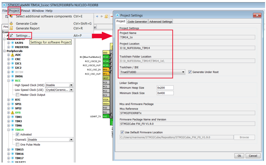
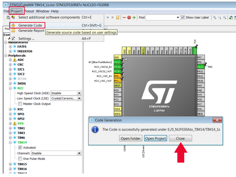
Now is time to generate the project for Atollic.
Do the configuration shown below.
We use the directory: E:\0_NUF030Ato_TIM14
and the project name is: TIM14_1s
Generate the project, see below.
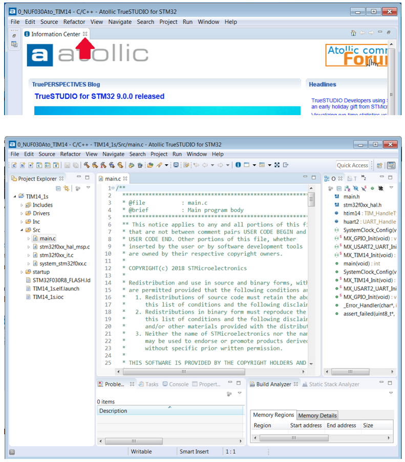
Now go in the directory: E:\0_NUF030Ato_TIM14\TIM14_1s
and double click on the file: .project
At this point the Atollic start and in the window that appear select the working directory that is: E:\0_NUF030Ato_TIM14
At the end, you must see something like below.
Close the advertising window.
The CODE
Now it’s time to insert the code, in the: main.c
for enable the flashing led at 1 second.
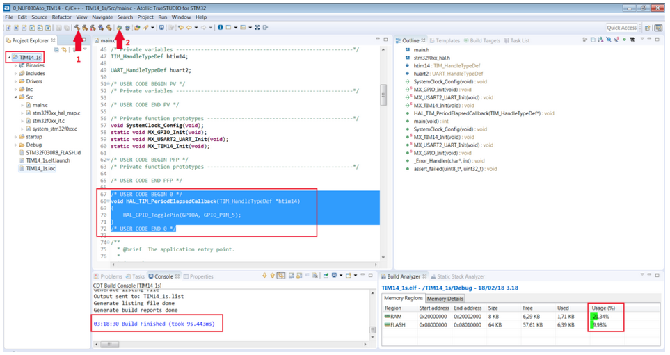
After the line:
/* USER CODE BEGIN 0 */
insert the Call Back, see below.
void HAL_TIM_PeriodElapsedCallback(TIM_HandleTypeDef *htim14)
{
 HAL_GPIO_TogglePin(GPIOA, GPIO_PIN_5);
}
Again, after the line:
/* USER CODE END 2 */
insert the line below,
HAL_TIM_Base_Start_IT(&htim14);
Now compile and debug.
You must see the led that flashing.
This solution works in Interrupt mode but request a computation section (Call Back) that commits the STM32 core.
It’s possible use the PWM timer functionality for flashing led that don’t use the STM32 core for running. See the next section.
FORMULA
In generl the formula for PERIOD calculation is:
T = (1/APB_TIM_CLK in MHz) * (PRESCALER_Value + 1) * (PERIOD_Value + 1)
suppose:
APB_TIM_CLK = 8MHz
PRESCALER_Value = 999
PERIOD_Value = 7999
the formula is:
T= (1/8*10^6) * (999+1) * (7999+1) = 1s
PWM mode
Now let’s see how to use the TIM14 (Basic Timers) (BT) in PWM mode, so we will flash the LED automatically without the MCU load.
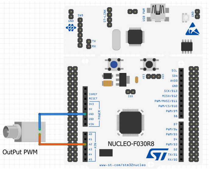
For use the TIM14 in PWM mode to drive directly a LED in necessary use the TIM14 CH1 PWM output that on STM32F030, is on PA4.
See the configuration below.
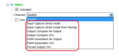
TIM14 -> ACTIVATED
CHANNEL1 -> PWM GENERATION CH1
The Clock must be configured as before (16 MHz), see below.
Now is necessary configure the TIM14, choose the CONFIGURATION tab, and see the below setups.

Now generate your project, we use the before configuration.
Go in the directory: E:\0_NUF030Ato_TIM14\TIM14_1s (Select the directory where you generated the SW)
and double click on the file: .project
At this point the Atollic start and in the window that appear select the working directory that is: E:\0_NUF030Ato_TIM14
The CODE
Now it’s time to insert the code, in the: main.c
for enable the flashing led at 1 second.
After the line:
/* USER CODE BEGIN 2 */
insert the line below,
HAL_TIM_PWM_Start(&htim14, TIM_CHANNEL_1);
Now compile and debug.
You must see the LED connected to PA4 flashing.
PA4 correspond to A2 label present on NUCLEO board (Arduino Connector on the left).
Suggestions:
Try to change the parameters:
htim14.Init.Prescaler – defult 999
htim14.Init.Period – default 15999
sConfigOC.Pulse – default 7999
in MX_TIM14_Init function and see the results.
Try this parameters:
Prescaler - Period - Pulse - Freq must be
   1         3999     1999        2 KHz
   1         1999      999        4 KHz
   1            4        2      1,6 MHz
How to get the SW for this PWM project
Please send us an email and ask us the password for: TIM14F0NU-PWM
Please specify also your country and your city, this are only for our personal statistics.
Get the SW clicking here, but remember to ask us the password for open it.
NOTE:
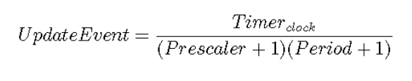
The Period and Prescaler registers determine the timer frequency, that is how long does it takes to overflow (or, if you prefer, how often an Update Event is generated), according this simply formula:
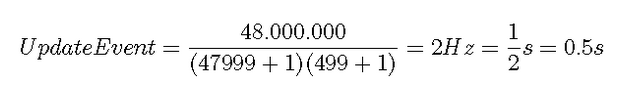
For example, assume a timer connected to the APB1 bus in an STM32F030 MCU, with the HCLK set to 48MHz, a Prescaler value equal to 47999 and a Period value equal to 499. We have that timer will overflow at every:
The max timer frequency is 12 Mhz with Prescaler and Period set both to 1.