
- Introduction
- STM32 library
- STM32 manuals
- Start to write the STM32 code
- Start STM32CubeIDE
- Clock Configuration
- Associate to a pin a function
- Change peripherals pins positions
- I/O parameters
- Project Manager
- Generate the project
- Insert a user code in the project
- Compile
- Debug
- printf via USB (Virtual COM)
- Watch variables
- Install STM32CubeIDE
- Import a Project in your WorkSpace
- Export your STM32CubeIDE project
- Switch the Workspace
- Example ready to use
- What happens to the power on of the STM32 ?
- Debugging C or ASM code
- Proprietary code read-out protection
- Take care also about the HW project for make a good product
- Power the NUCLEO using an external USB power supply
- Note on FIREFOX and CHROME
- Appendices
- How to optimize code generation (hex)
- How to generate hex file
Introduction
For create a new project for STM32 first install the STM32CubeIDE and also you need to have an STM32 eval board, we suggest to use a NUCLEO 64pins boards that are not expensive and is possible buy it on Internet.
The official documentation regarding STM32CubeIDE is: UM2609 – STM32CubeIDE user guide
See here for know how to install STM32CubeIDE.
STM32 library
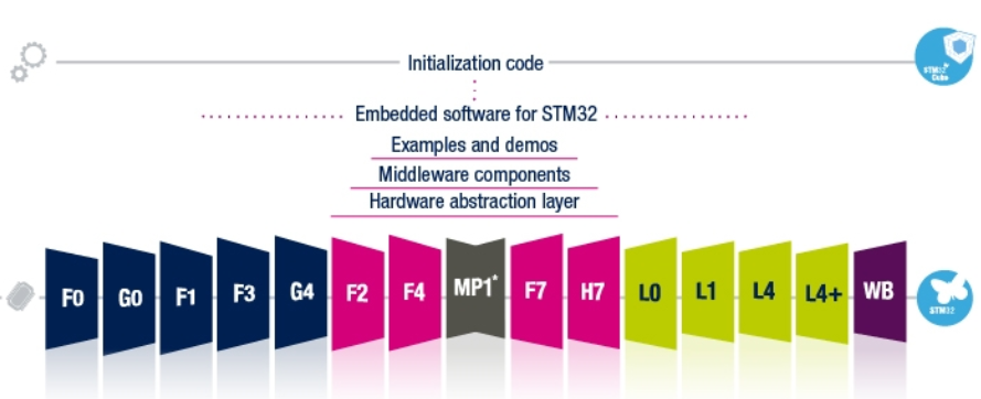
It’s also necessary download the STM library package for the STM32 families that you decide to use. (G0, F0, L4, F4…H7).
The library contain:
Examples (I/O, USART, I2C, ADC, DAC, SPI, CAN, DMA, etc)
Middleware components (USB, TCP/IP, Graphics, FAT file system, etc)
HAL and LL functions
The Hardware Abstraction Layer (HAL) enabling portability between different STM32 devices via standardized API calls
Low Layer (LL) APIs, a light-weight, optimized, expert oriented set of APIs designed for both performance and runtime efficiency
Both the HAL and LL APIs are production-ready and have been developed in compliance with MISRA-C®:2004 guidelines with some documented exceptions (reports available on demand) and ISO/TS 16949.
Furthermore, ST-specific validation processes add a deeper-level qualification.
In our case we decide to use the STM32F401RE and the NUCLEO-F401RE and so we download the F4 library.
NOTE:
In any case, feel free, to choose the STM32 evaluation boards that you prefer.
The concepts present in this page are the same for any STM32 families.
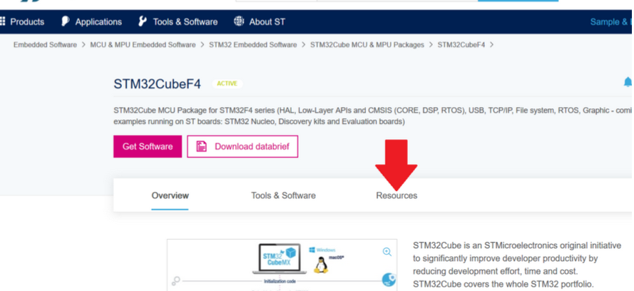
For know the functions that are available for drive the MCU is necessary download the User Manual that describe the HAL and LL functions, this is a big manual and is in the Resources -> User Manuals section, see below.:
In our case the manual is: UM1725 – Description of for STM32F4 HAL and LL driver
STM32 manuals
As we mentioned above, for this first example we use the NUCLEO-F401RE but you must use any STM32 eval board.
On the board there is the STM32F401RE (LQFP64), it’s important remember that for any STM32 there is 3 fundamental manuals that are:
Data sheets (DS)
Reference manual (RM)
Errata sheets (ES)
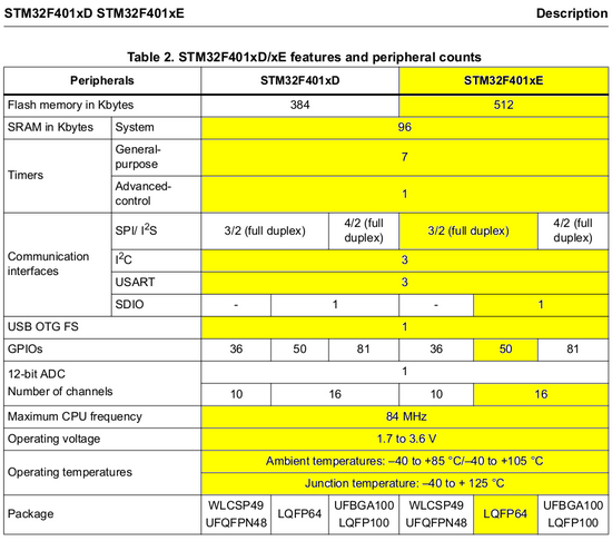
Normally the Data Sheets (DS) cover a lot of similar MCU, for know which peripherals, how many I/O, Flash, etc, you has in your particular mcu open the DS and go to the page named DESCRIPTION and look the column on the vertical of the name of your mcu and package, see the below example, yellow boxes.
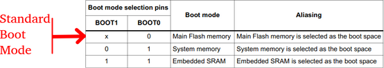
Reference Manual is very important for know in deep the Peripherals, the Boot Mode Configuration pins, the Embedded bootloader and the Memory Mapping of your STM32.
Below there is the 512KFlash memory map of the STM32F401RE.
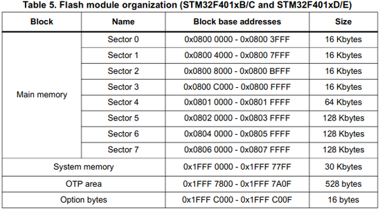
Note that address of the flash is contiguous (linear address) but is divided in 8 sector. Flash start at the address 0x0800 0000 and finish to the address 0x0807 FFFF.
The first instruction of your program is stored at the address 0x0800 0000.
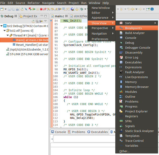
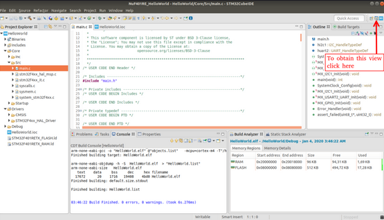
Of course, using the STM32CubeIDE is possible see the contents of FLASH, RAM, REGISTER, etc, see below the DEBUG -> WINDOW -> SHOW VIEW
NOTE:
The System Memory is ROM and is written by STM for store Boot Loader and other self test routine..
Errata sheets manual is aging important to know eventually problems find in mcu and the work around solution that STM propose.
Start to write the STM32 code
Now is time to write some piece of code for STM32.
Our goal is blinking the green LED (it’s connected to PA5) that is present on the NUCLEO-F401RE and send data via USB (virtual COM) to the PC.
On PC we use, for Windows the Tera-Term and for Linux we use the Minicom or GtkTerm, for see the results.
For this example we use the NUCLEO-F401RE.
NOTE:
In any case, feel free, to choose the STM32 evaluation boards that you prefer.
The concepts present in this page are the same for any STM32 families.
First install on your PC the STM32CubeIDE and the terminal emulator (on PC we use, for Windows 10 the Tera-Term and for Linux we use the Minicom or GtkTerm).
For our example we use a PC with Linux but is the same for PC with Windows 10.
After the installation of STM32CubeIDE run it.
Start STM32CubeIDE
The official documentation regarding STM32CubeIDE is: UM2609 – STM32CubeIDE user guide
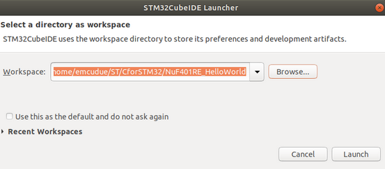
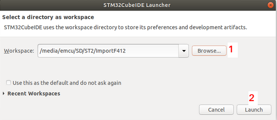
At start up the STM32CubeIDE ask you to specify the working directory for your project, choose (BROWSE button) one and press lunch, see below.
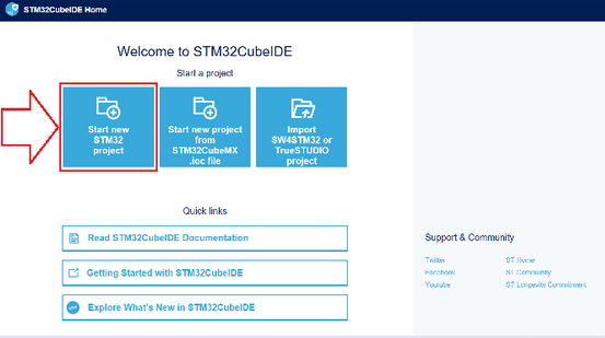
Now you must see a window like below, choose: START NEW STM32 PROJECT
Now will compare a box where the STM32CubeIDE download the update from Internet, be patience.
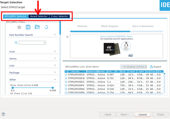
From the window that appear you have the possibility to choose an STM32 (MCU/MPU Selector) or an evaluation board (Board Selector), we choose Board Selector, see the image below.
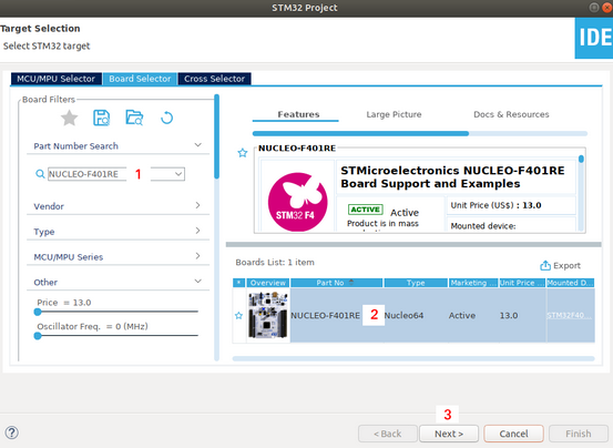
From the window that appear, write NUCLEO-F4101RE (or the name of your STM eval board) in the find box (1) next select the board (2) and press NEXT (3), see below.
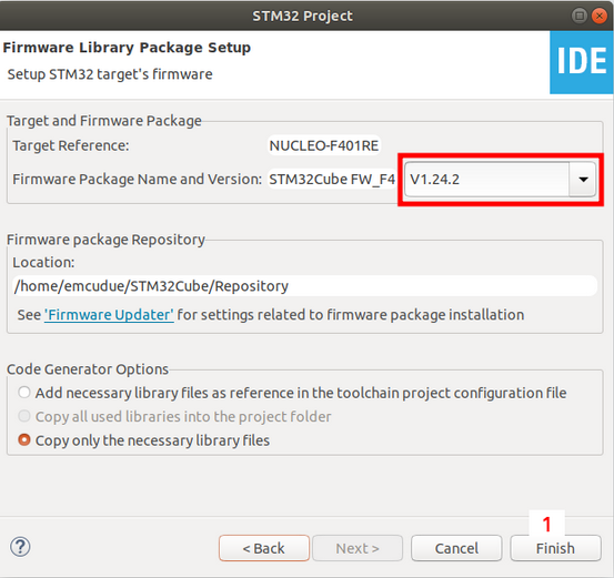
From the window below you have the possibility to choose the release of the library to use.
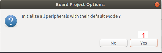
From the window below choose YES because in this way you get the right configuration for your evaluation board.
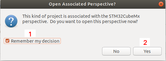
From the window below choose YES for open also the MX tab for configure I/O, peripherals, etc.
The first time that you use a new STM32, the STM32CubeIDE will download the related library from STM website. Be patience.
At the end of the download you must see a window like below.
NOTE:
We highlight to you that:
* Green LED is allocated to PA5
* Blue Button is allocated to PC13
* Usart TX and Usart Rx are allocated to PA2 and PA3.
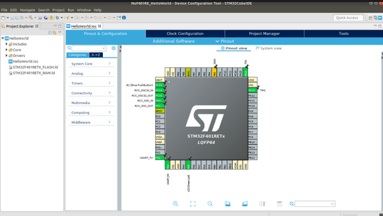
For know which Usart is, click on CONNECTIVITY and you will discover that is USART2.
The USART2 is connected to the STLINK-v2 (remember that this emulator is embedded in all STM evaluation boards) and is possible send/receive character via the USB used by the emulator (virtual COM).
The colored pins are pins allocated, the gray pins are free<
Clock Configuration
If you click on the CLOCK CONFIGURATION tab, the perspective change and you see the clock tree, see below.
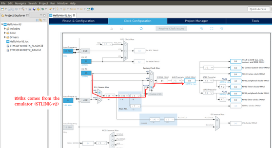
The 8Mhz clock comes from the STLINK-v2.
In the case below the HCLK clock (it’s the core clock of the MCU) is generated starting from the internal HSI RC oscillator, see the red line.
NOTE:
All STM32 has 2 or more internal clock source, consult the relative DS.
Also the precision of this internal clock depend of the STM32 that you use.
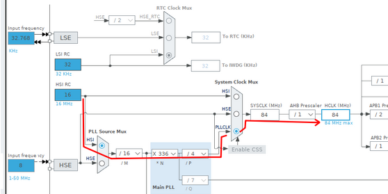
84 Mhz (HCLK) is the max frequency of the STM32F401RE.
If you need decrease this frequency simply select 84 and insert a new integer number, try with 16 and with 100.
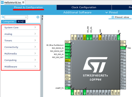
Associate to a pin a function
If you need associate to a pin a function, click on pin and from the selection box that appears, select the functionality that are possible to associate to the relative pin.
This way to operate is recommended for allocate I/O pins but is not recommended for allocate the peripherals pins.
For allocate the peripherals pins is recommended to select the:
System Core
Analog
Timers
etc
See below.
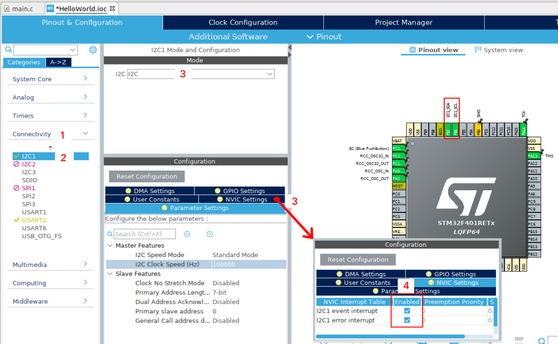
Suppose that you need to use also an I2C, do the steps below.
First select CONNECTIVITY tab(1), next choose an available I2C (2)(the red peripherals means that are not available because some other peripherals use the same pins) next configure it (3 and 4).
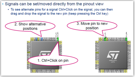
Change peripherals pins positions
NOTE:
Most of principal peripherals pin are possible to move on another pins, see below.
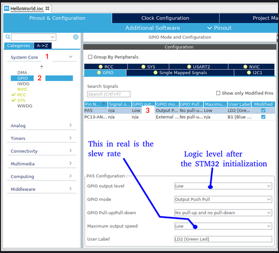
I/O parameters
Interesting is the possibility to configure the I/O pins, see below.
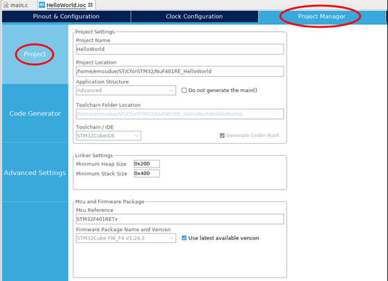
PROJECT MANAGER
Now select the PROJECT MANAGER tab, you must see the below window.
In the PROJECT tab you can decide the dimension of HEAP and STACK, live the preset value if you don’t have a particular necessity.
HEAP and STACK can also be changed later in your SW.
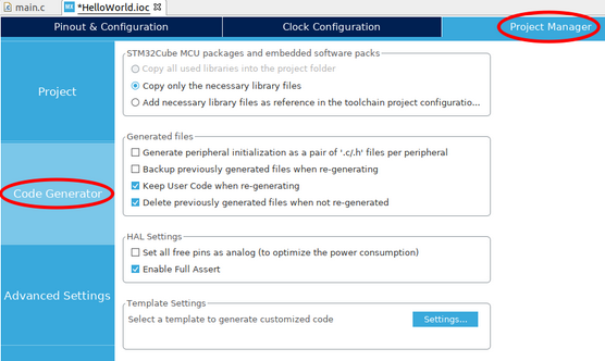
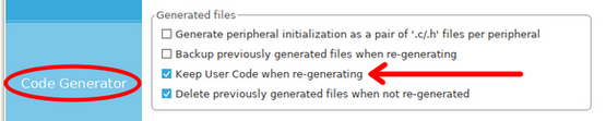
In the Code Generation tab set the flags as shown below.
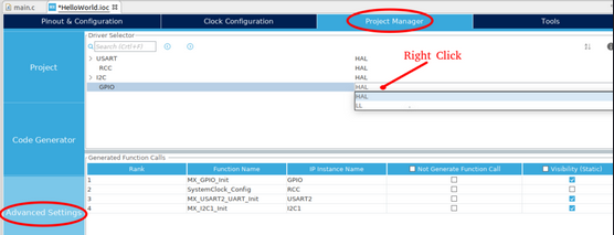
In the ADVANCED SETTINGS there is the possibility, for any peripherals, to choose the HAL or LL functions.
It’s important that you use in your sw the right functions you had choose for your peripheral.
In other words, if you decide to use UART1 in LL mode do not use the HAL functions on USAT1 to avoid a fatal fault on mcu
In general for battery application we suggest to use the LL and in the other case we suggest to use HAL.
For our necessity all peripherals and I/O are now configured, now is possible generate the project.
NOTE:
The project is created for GCC because STM acquired ATOLLIC and integrated it in the STM32CubeIDE.
On this website under:
MCU -> ATOLLIC
you can find a lot of examples, tips and tricks for Atollic that are compatible with STM32CubeIDE.
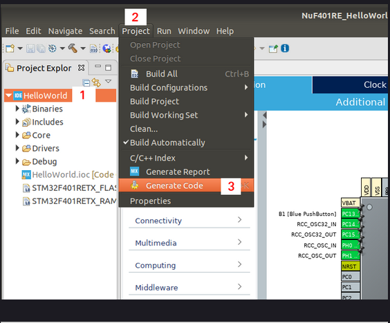
Generate the project
For generate the project follow the steps below (1, 2 and 3).
You may have noticed that in the PROJECT menu you can also generate a REPORT (Generate Report), try using it and look at the relative PDF.
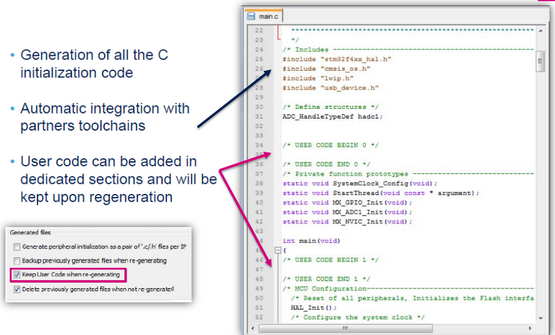
Insert a user code in the project
The image below is for highlight that is a good practice insert your code in the dedicated sections that begin with
/* USER CODE BEGIN xxx */
and ended with
/* USER CODE END xxx */
If you respect this, you can back to the DEVICE CONFIGURATION TOOL to do a change, regenerate the code and preserve your code.
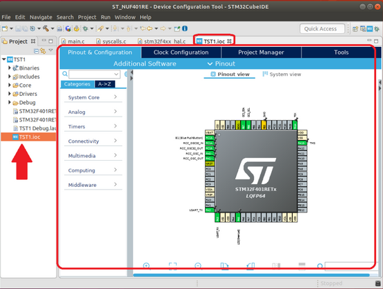
Open the main.c
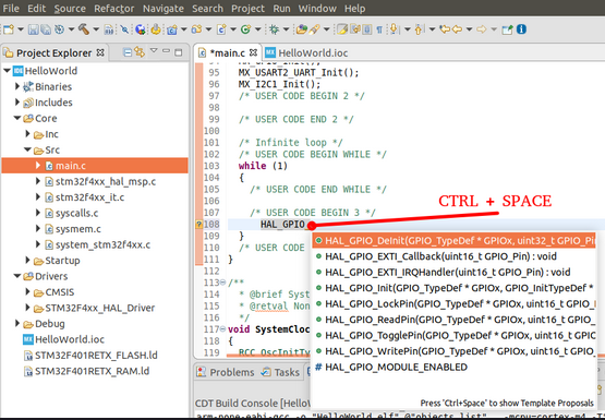
Now start to insert the C lines and if you don’t remember exactly the syntax, after write some letters of the command press:
CTRL + SPACE
and will compare a pop up windows, see below
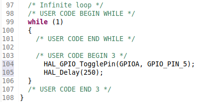
OK, the two line to insert for blinking the green LED present on the NUCLEO-F401RE are: HAL_GPIO_TogglePin(GPIOA, GPIO_PIN_5);
HAL_Delay(250);
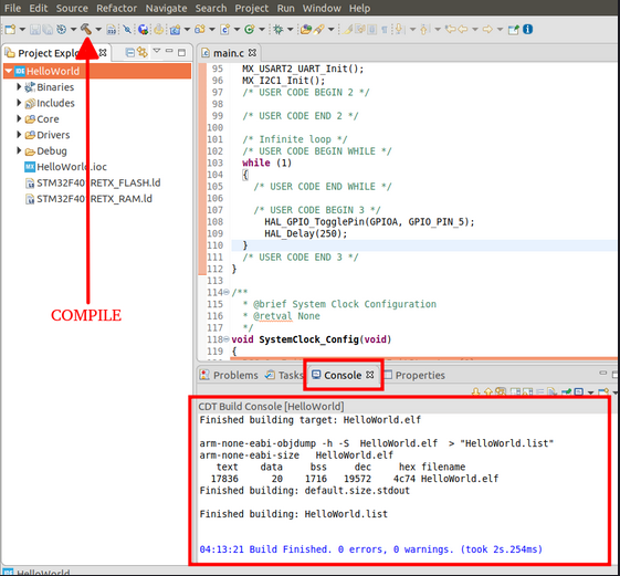
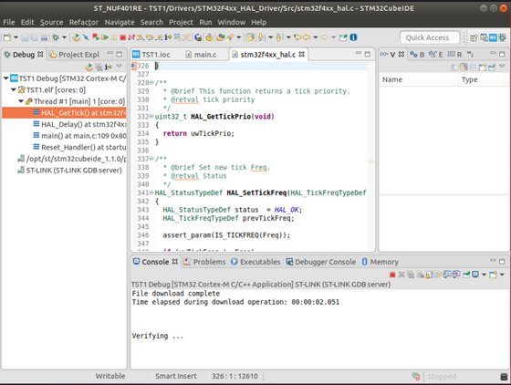
Compile
Now select you project name and compile it.
You must see something like below.
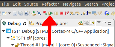
Debug
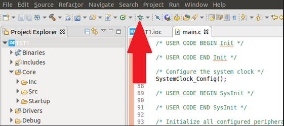
Now connect your STM eval board to your PC and click on the DEBUG icon.
See below.
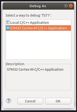
From the window that appear select: STM32 Cortex-M C/C++ Application
and press OK, see below
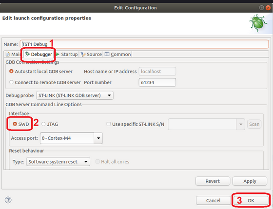
The first time that you enter in debug will appear the window below, in the DEBUGGER tab verify that is selected SWD, next press OK, see below.
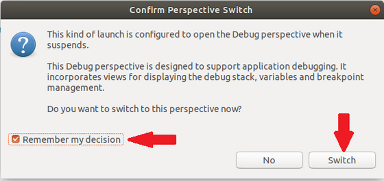
At this point will appear the window below, set the flag: Remember my decision
and next click on: switch
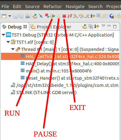
Now will appear the debug window, see below.
In the debug perspective there are a lot of commands/icons available, for the moment press on the RUN icon and look your NUCLEO-F401RE, you must see the green LED that blinking.
For stop the RUN of your program press the PAUSE icon.
For exit from the debug perspective press the EXIT icon.
For continue the RUN of your program press again RUN icon.
See below.
printf via USB (Serial COM)
Perfect, the first step of our program is running, now we show you how to insert a printf that use the emulator for send a data via virtual COM, see the image below.
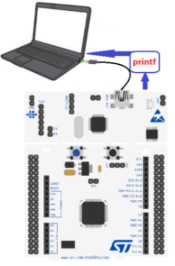
For implement the printf via USB port is necessary redirect the PUTCHAR to USART2.
Insert from:
/* USER CODE BEGIN PV */
and
/* USER CODE END PV */
the code below.
int nLoop=0;
Insert from:
/* USER CODE BEGIN 4 */
and
/* USER CODE END 4 */
the code below.
int __io_putchar(int ch)
{
uint8_t c[1];
c[0] = ch & 0x00FF;
HAL_UART_Transmit(&huart2, &*c, 1, 10);
return ch;
}

int _write(int file,char *ptr, int len)
{
int DataIdx;
for(DataIdx= 0;
DataIdx< len; DataIdx++)
   {
   __io_putchar(*ptr++);
   }
return len; }
ATTENTION
From the above code, the sw refer to huart2 that is the handler of the USART2 that is connected to ST-LINK emulator for exit like a virtual com.
Normally on the 64pin NUCLEO is used the USART2 (huart2) but on 144pin NUCLEO the USART is USART3 so the handler to use is huart3.
Insert from:
/* USER CODE BEGIN Includes */
and
/* USER CODE END Includes */
the code below.
#include <stdio.h>
Insert from:
/* USER CODE BEGIN 3 */
and
/* USER CODE END 3 */
the code below.
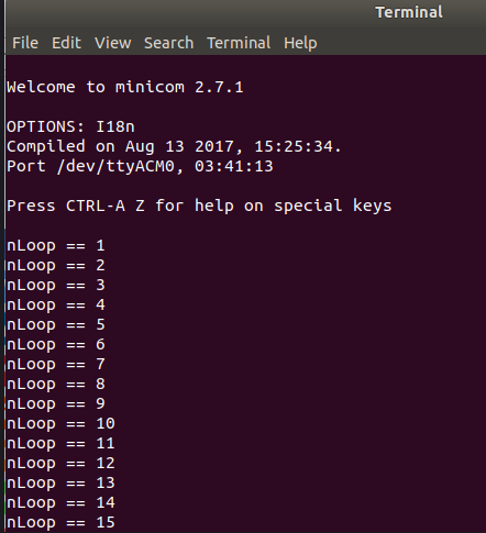
 nLoop++;
 printf("nLoop == %d \n\r", nLoop);
That is all, compile and test your code. Remember to run MINICOM (or GtkTerm) or Tera-Term for see the results.
How to get the SW ready to use, for above project
Please send us an email and ask us the password for (Ref.Cod.):
Printf-NUF401RE
Please specify also your country and your city, this are only for our personal statistics.
Get the SW clicking here, but remember to ask us the password for open it.
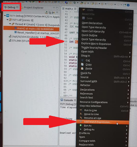
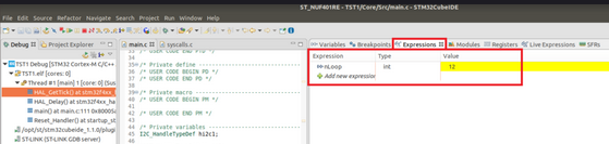
Watch variables
The last thing that we show you is the way to watch your variables in a watch window.
In DEBUG select the variable: nLoop, and next click right.
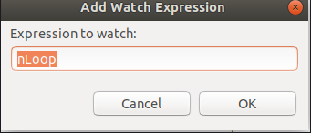
From the window that appear select: Add Watch Expression
and from the window that appear select: OK
see below.
Now try to RUN, STOP, RUN and STOP your program and see the variable.
Thanks to our friend prof. Angelo Pietro Pennisi now there is the related video.
Extra Information
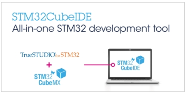
How to install STM32CubeIDE
The examples that you can find here are for STM32 mcu and for develop our examples we use the STM32CubeIDE.
STM32CubeIDE data brief is here.
STM32CubeIDE documentations are here.
The features of STM32CubeIDE are below.
For us one of the best feature is that it’s a multi platform tool because we use LINUX (Ubuntu).
Also the STLINK-v2 (is STM32 low coast emulator) is 100% compatible with Ubuntu.
NOTE: The STLINK-v2 is embedded in all STM32 eval boards.
- Integration of STM32CubeMX that provides services for:
- STM32 microcontroller and microprocessor selection
- Pinout, clock, peripheral, and middleware configuration
- Project creation and generation of the initialization code
- Based on ECLIPSE™/CDT, with support of ECLIPSE™ add-ons, GNU C/C++ for Arm® toolchain and GDB debugger
- Additional advanced debug features including:
- CPU core, peripheral register, and memory views
- Live variable watch view
- System analysis and real-time tracing (SWV)
- CPU fault analysis tool
- Support of ST-LINK (STMicroelectronics) and J-Link (SEGGER) debug probes
- Import project from Atollic® TrueSTUDIO® and AC6 System Workbench for STM32 (SW4STM32)
- Multi-OS support: Windows®, Linux®, and macOS®, 64-bit versions only
We use the UBUNTU 18.04.3 LTS (a Linux version).
If you use Linux Ubuntu download STM32CubeIDE, unzip it, change the permission of the file:
st-stm32cubeide_1.1.0_4551_20191014_1140_amd64.deb_bundle.sh
and in the terminal do the commands below:
sudo su
chmod +x st-stm32cubeide_1.1.0_4551_20191014_1140_amd64.deb_bundle.sh
next install it:
./st-stm32cubeide_1.1.0_4551_20191014_1140_amd64.deb_bundle.sh
NOTE:
On your PC (host) it is possible to add additional compilers for example for Linux or for Windows and use it inside the STM32CubeIDE.
For install the compiler for Linux do the commands below:
- sudo su
- apt update
- apt install build-essentia
After the above commands on your Linux there is the GCC compiler for your PC.
Now is possible use the STM32CubeIDE also for write a C code for your PC (Host).
For more info see here.
For know the version of the installed GCC use the command below:
gcc –version
You must see an answer like below:
gcc (Ubuntu 7.4.0-1ubuntu1~18.04.1) 7.4.0
Copyright (C) 2017 Free Software Foundation, Inc.
This is free software; see the source for copying conditions. There is NO
warranty; not even for MERCHANTABILITY or FITNESS FOR A PARTICULAR PURPOSE.
Import a Project in your WorkSpace (using STM32CubeIDE)
Suppose that you receive a .zip project from your friend for STM32CubeIDE, for import it in your workspace do this:
Run STM32CubeIDE and choose a directory for import the project that you had received. See below.
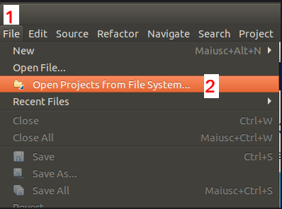
From the window that appear select:
FILE -> Open Projects from File System…
see below
Now, from the new window that appear do the steps from 1 to 4.
See below.
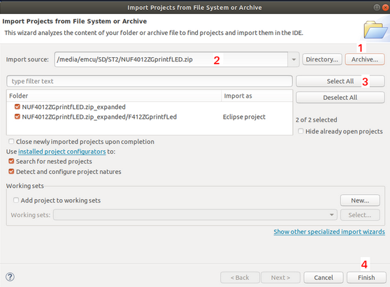
This is all, automatically STM32CubeIDE import the .ZIP project that you received.
Below there are the steps for compile and debug.
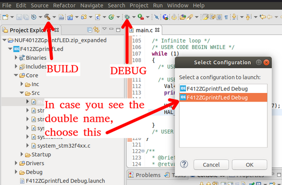
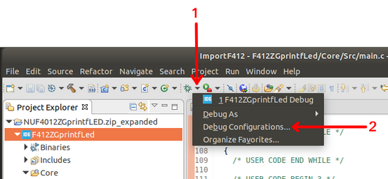
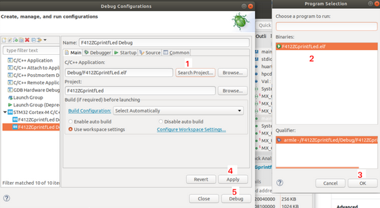
Sometimes is possible, that the first time that you enter in debug, appear the error below.
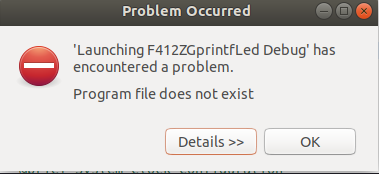
Press OK and choose the debug configuration, see below.
The problem is a little bug present in the current release of STM32CubeIDE that is easy to resolve, simply do the steps below and the debug will work well.
TEST – import a project
For check if you understood all, download this project and import it into your STM32CubeMX working directory.
This example is for NUCLEO-F401RE and do blinking the green LED.
At the end of your import & compilation you must see something like below.
Export your STM32CubeIDE project
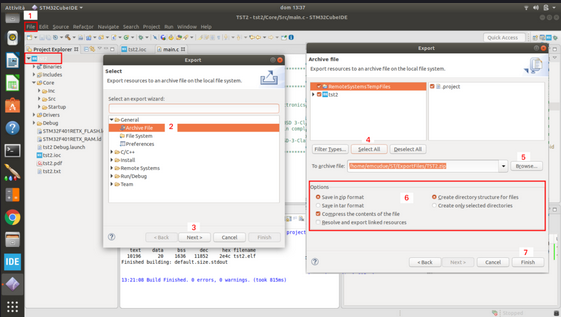
For export a project do this:
FILE -> EXPORT
and from the new window that appear select:
GENERAL -> ARCHIVE FILE then press NEXT
and in the new window that appear choose:
SELECT ALL (4)
next do the steps 5, 6 and 7, see below.
STM32CubeIDE – Switch the Workspace
For change your workspace you have two possibility that are:
Close the STM32CubeIDE and reopen it choosing a new workspace directory or…
choose: FILE -> Switch the workspace -> Other…
choose your new workspace and select LUNCH.
How to get the SW ready to use for this project
Get the SW clicking here.
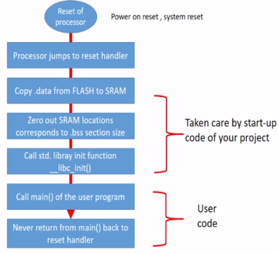
What happens to the power on of the STM32 ?
At the power-on there is an initialization sequence that stabilize the clocks of mcu and copy in RAM from FLASH the variables.
This code is in assembler and is released by the mcu producer.
After this part of initialization, the sw you wrote is launched.
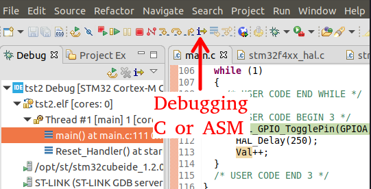
Debugging C or ASM code
When you enter the first time in debug mode for default you debug the C source code.
If you need debug the ASM code click on the icon qui sotto.
AN4701 – STM32F4 proprietary code read-out protection
Last but not list is very important protect your code, for a deep explanation see the AN4701.
Fundamentally there are 3 level of protection that are:
Level 0 – Level 0 is the default one, Flash memory is fully open and all memory operations are possible in all boot configurations (Debug features, Boot from RAM, from System memory bootloader or from Flash memory).
In this mode there is no protection (it is mainly intended for development and debug).
Level 1 – When the read protection level 1 is activated, no access (read, erase, and program) to Flash memory or backup SRAM can be performed via debug features such as Serial Wire or JTAG, even while booting from SRAM or system memory bootloader.However, when booting from Flash memory, accesses to this memory and to backup SRAM from user code are allowed.
Any read request to the protected Flash memory generates a bus error.
Disabling RDP level 1 protection by re-programming RDP option byte to level 0 leads to a mass erase.
Level 2 – When RDP level 2 is activated, all protections provided in Level1 are active and the chip is fully protected.
The RDP option byte and all other option bytes are frozen and can no longer be modified.
The JTAG, SWV (single-wire viewer), ETM, and boundary scan are disabled.When booting from Flash memory, the memory content is accessible to user code.
However, booting from SRAM or from system memory bootloader is no more possible.
This protection is irreversible (JTAG fuse), so it’s impossible to go back to protection levels 1 or 0.
Take care also about the HW project for make a good product
Up to now we spoke about the SW but don’t forget to apply extreme care also to the project of your HW.
Remember that your SW need a robust HW to work right an vice versa.
Your end product is a mix from HW & SW.
Use all time that is necessary during the HW project phase to avoid future problems. Remember that you develop a embedded HW/SW that must work without human supervision, release your project only when you are satisfied with it.
Remember that people will only see the final product but not your effort and the time you have spent to make it.
Your efforts will be rewarded by the appreciation of your final product.
For avoid HW problem see in your know how and don’t avoid to read the application note listed below.
- The below manuals are in WWW.ST.COM website.
- AN1709 – EMC design guide for STM8, STM32 and Legacy MCU
- AN3960 – ESD considerations for touch sensing applications on MCUs
- AN5036 – Thermal management guidelines for STM32 applications
- AN4299 – Improve conducted noise robustness for touch sensing applications on MCUs
- AN3307 – Guidelines for obtaining IEC 60335 Class B certification for any STM32 application
- Getting started hardware development is available for all STM32 family, find it in the page of STM32xxx that you need to use. AN4080 is for STM32F0 family.
- Oscillator design guide for STM8S, STM8A and STM32 microcontrollers, AN2867 is here
- Calibrating internal RC oscillators is available for all STM32 family, find it in your STM32 that you need to use. AN4067 is for STM32F0 family.
- AN4657 – STM32 in-application programming (IAP) using the USART
- AN1181 – Electrostatic discharge sensitivity measurement
- AN4879 – USB hardware and PCB guidelines using STM32 MCUs
Appendices
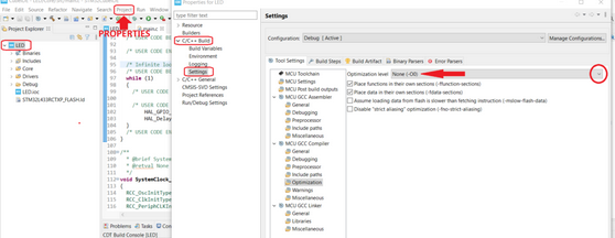
Optimization
To optimize the size generated by the STM32CubeIDE, select -Os, see image below.
Project -> PROPERTIES -> C/C++ Build -> Settings -> Optimization
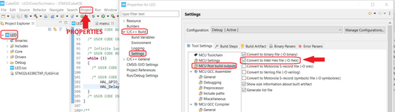
hex file
For generate the hex see the configuration below.
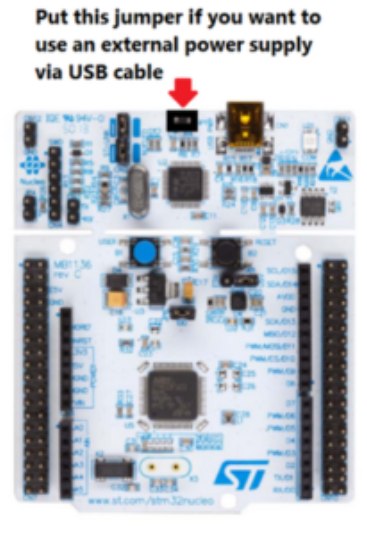
Power the NUCLEO using an external USB power supply
Note on FIREFOX and CHROME
Use FIREFOX or CHROME for a clear view of the images present in this web site
For enlarge the image press: CTRL +
For reduce the image press: CTRL –